Chapter 7 – Getting Started
Getting Started
- Clean out (blow) 2″ airline before hooking up.
- Hook up 2″ airline to air inlet with whipchecks to all airline connections.
- Make sure all switches are turned to the off position.
- Make sure battery is hooked up and fully charged.
- Hook up all vacuum hoses with cam-locks.
- Hook up all discharge hoses make sure all discharge hoses are tied down & secured.
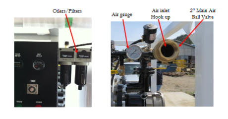
- Slowly turn on main air valve make sure air gauge is around 80 to 120 PSI.
The PV500 is fitted with a lubricator and a filter to lubricate and also protect the controls from any debris in the control air. The filter also separates water from the air stream and should be drained daily by turning the bottom valve clockwise. Since humidity in the air changes daily it is a good idea to check this often to determine the actual emptying intervals. The oiler is controlled by a valve in the top cover, counter-clockwise allows more oil into the system. A quarter turn or a drop a minute is sufficient to operate. Use clean air tool or pneumatic oil to fill the oiler daily.
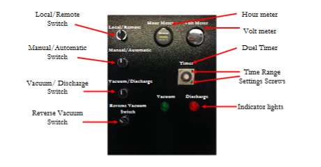
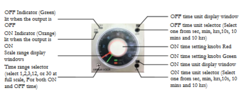
Turn the Automatic/Manual switch to the manual position, turn the Vacuum/Discharge switch to the discharge position for a few seconds, and then to the vacuum position for a few seconds to make sure everything is working; don’t worry you can’t damage anything by running it dry. Then put the switch to the automatic position, it will start on discharge. To start, put your duel timer 30 secs to vacuum and 30 secs to discharge. You set the timer range settings by adjusting the time range screws as shown, this can be seen in the indicator window in hrs, mins, 10s and secs. Put your nozzle in your material and start pumping, you will be able to hear when your tank is full and when your tank is empty, set your timers and again, don’t worry you can’t damage anything by over filling your tank, the more you run it the more you will get to know the machine and how to set it, this should only take a few trials.
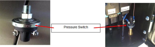
Pressure Switch
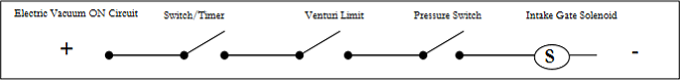
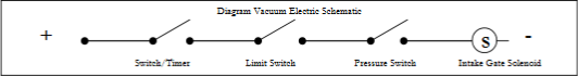
The pressure switch is an important part of the PV500’s safety system, it is wired in series with the venturi gate limit switch to ensure that the intake gate will not open with the tank pressurized. Do not disengage these important systems.
How it works
The pressure switch senses the tank pressure and in conjunction with the venturi limit switch makes sure that there is no pressure in the tank before the intake gate opens. When the vacuum unit goes into vacuum mode, power is allowed to operate solenoid valves that control the opening of the gate valves. The venturi gate opens first and that lets the tank become open to atmosphere before the intake gate will open. When the venturi gate opens it activates the venturi gate limit switch, which in turn with the pressure switch allow the intake gate to open. If the intake gate fails to open during vacuum cycle the limit and pressure switch should be checked for correct operation.
Care and Maintenance
The limit switch should be checked to be sure that when the venturi gate opens, the actuator rod on the knife-gate closes the limit switch when the venturi gate is fully opened.The line to the pressure switch must be checked to be sure that the line is clear to the pressure switch located in the panel. The pressure switch makes sure that if the pressure is too high the gate will not open, the values should be determined by qualified operators and no material changes should be made to these systems or parts of this safety system without consulting IVAC. Adjusting pressure is accomplished by removing the rubber plug in the end of the pressure switch(PS) and with a hex head wrench turning it in (clockwise) to raise the pressure and out (counter-clockwise) to lower the pressure. An alternative pressure switch is available for low pressure systems and a complete vacuum can be used for sensing a vacuum before the intake gate will open. The PV500 Unit comes equipped with the regular pressure switch that is used for general applications. Discuss this with IVAC technical support for additional information.
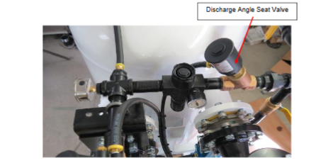
Discharge Air Angle Seat Valve
The discharge air angle seat valve allows air to energize the discharge air to evacuate the tank of your picked up materials. The valve is operated via the intake limit switch and the control circuit by ensuring that the intake gate is closed before discharge air is allowed to turn on. This prevents any pressure from reaching the operators line/hose. If the unit fails to discharge when on “discharge” mode, check the intake gate limit switch for its’ correct operation.
How It Works
When the PV500 is in discharge mode, electric power energizes the intake gate limit switch. When the intake gate is closed and therefore closes the intake gate limit switch (ILS) circuit-energizing solenoid #5 (Discharge Mode) turning on air into the pilot line leading to the discharge air angle seat valve. The pilot pressure in turn opens the discharge air angle seat valve allowing air to flow into the vessel/tank by going through the discharge air regulator and the two X 1″ ball valves that control the discharge air pressure and volume.
This procedure ensures that the intake line will not receive any pressure to the operators pick up line.
Care and Maintenance
The angle seat valve is a pilot operated pneumatic solenoid. When the pilot line is charged (on) it turns on the larger discharge angle seat valve. The pilot airline should be checked for wear and ensure that the connections are tight and there are no leaks. Air pipes leading to and from the valve should be tight and have no leaks.
Main Air Angle Seat Valve
The main air angle seat valve allows air to travel through the venturi to create a low pressure area in the vessel. Atmospheric pressure pushes material into the vessel thorough pipelines and/or hoses connected to the intake cam-lock fitting. The main-air/vacuum-air angle seat valve is activated by the control solenoids in the main control panel.
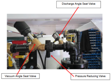
Discharge Pressure Reducing Valve
The pressure reducing valve on the discharge line allows the operator to set the discharge air pressure from zero to compressor system pressure while maintaining the volume of air needed to evacuate the material from the tank. The pressure reducing valve should be set at a pressure to move the material from the tank and through the hoses and pipes as required. The pressure should be kept as needed and not too high so as not to create fly rock or splashing of material or cause premature wear on discharge piping parts. Too high of pressure can create a safety issue and all lines leading from the unit on the discharge line must be of good construction and rated for the pressures. Discharge piping and hoses need to be securely anchored.
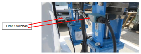
Limit Switches
There are two limit switches located on the IVAC PV500 unit. The limit switches are an integral part of the unit’s safety system and must not be by-passed. The limit switches ensure that the intake and discharge gate positions are in the proper position before opening of the intake gate or turning on of discharge air are allowed to continue
How they Work
In order to ensure that the pressure vessel contains low/zero pressure before the intake gate is permitted to open. The venturi limit switch works in series with the pressure switch located in the electric panel.
When the vacuum unit goes into vacuum mode, electric power is used to operate the MAC solenoid valves that control the opening of the inlet and venturi gate valves and the closing of the discharge knife-gate valve. When in vacuum mode the venturi gate opens first & therefore opening the tank to atmosphere that causes low tank pressure before the intake gate will open. This is meant to bleed off any remaining pressure in the tank. When the venturi gate opens it closes the venturi gate limit switch which is connected in series to the pressure switch. Once the pressure switch senses low tank pressure it allows the intake gate to open. If the intake gate opens and allows air into the inlet hose prematurely, the discharge line could be plugged or the pressure switch requires adjustment.
On Discharge Mode, to operate the discharge air solenoid and subsequently pressurizing the holding vessel/tank, the intake gate limit switch is closed/activated indicating that the intake gate valve is closed. When the intake gate is closed, discharge air is allowed to enter the tank by turning on the discharge air angle seat (DASV) valve to discharge the picked up materials.
Care and Maintenance
The limit switch should be checked for tight mounting bolts. The arm/lever checked for proper setting and actuation point. The strain relief should be tight on the cable to ensure that no water can enter the switch and that the cable is held tight.