Chapter 5 – Discharge Valves
Discharge Valves
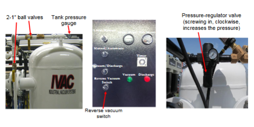
Discharge air – there are two 1″ manual ball valves located on the pressure vessel.
These valves help control the amount of air entering the tank during discharge mode.
The valves may be adjusted to control the discharge depending on the operation or material being moved.
There is a pressure regulator valve located on the discharge lines; this PR valve enables the operator to set the flow rate (pressure) of material through the discharge line. If discharging into a car, skip etc it can be adjusted lower to prevent material splashing or fly rock.
Important: If a Discharge line is plugged your tank pressure will be up and stay up. If so,put your switch to manual and on vacuum after you turn/hold your reverse switch (this will prevent the intake gate from opening) on for about 5 seconds, it is spring loaded and will return back to the off position. Using this function will turn your discharge line into a vacuum line for a few seconds and should dislodge the plug, repeat this process if required until the discharge line runs free again! Do not take apart any lines or clamps unless you have verified that the line does not contain any pressure. A One Inch valve (pictured next page) is installed to manually purge the pressure vessel of air.
NOTE: If the reverse vacuum switch is not held, air many escape from the inlet line!
IMPORTANT NOTE: This valve will purge the pressure vessel only.